| Previous article | Next article |
Determining the Differential Constant of a Gear Hobber with Precision
This article builds on the previous article about a Seiwa MD600 hobber which showed how to look at a new hobber when its manual is not available. Here, Mr. Lehman develops a practical way to accurately measure an unknown Differential Constant by accurately measuring actual lead of a gear cut by your gear hobber.
Mr. Lehman makes use of a milling machine, geared index head and dial indicator to simulate a lead checking machine. Although the purpose here is to improve on his hobber's differential constant, it also describes a perfectly adequate method to find the unknown lead or helix angle of a sample gear you might plan to duplicate.
To implement the following procedure, you will need a setup as shown below:1st Step: Make a helical gear on the gear hobber (the first article can help you cut a sample helical gear). As recommended in the first article you might visit MeshingWithGear’s FAQ Hobbing Topics to explore differential constant.
After cutting your first helical gear, you should already have a reasonably accurate figure for the machine's differential constant ("Working" differential constant for Seiwa was approximately 0.31327). The gear specs that follow are a bit different from those of the first article.
The Seiwa's index constant = 24, or 24/N. The index gear set ratio was made 1:1, so the number of teeth (N) to cut is 24.
An 8 NDP hob is available.
Since actual gear helical angle is not important, we select the following differential changegears from a limited inventory:
A/B X C/D = 68/58 X 60/79 = 0.8904408555 (differential ratio)
Thus our helix angle (HA) will be according to the following formula:
sin(HA) = differential ratio / (differential constant X NDP)
8 NDP hob is selected for the trial gear, therefore,
sin(HA) = .8904408555 / (0.31327 X 8) = .355300
HA = 20.8118 degrees
At this point, we know the following;
the Normal Diametral Pitch = 8
the helix angle = 20.8118 degrees
the number of teeth = 24
The OD of the blank is calculated as:
OD = Teeth/(NDP X COS(HA)) = 3.4594
Then the gear is cut.
Now using a gear handbook, the following can be computed:
Addendum = 0.125000
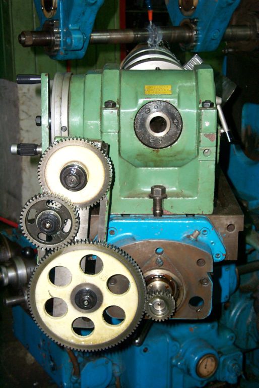
Lead = pi X Teeth/[NDP X sin(HA)] = 26.5262925 2nd Step: Referring to the picture above,The alignment (all planes and axis) is critical to the accuracy of the final result. Spend time making sure you have everything properly aligned. (A good way is to mount a precision ground rod between centers and indicate the front side (and back side to assure no taper) of the rod as you move the table. There should be "0" indication. 3rd Step: Mount the gear as shown in picture below. Mount a dial indicator as shown but keep the contact tip away from the gear until you have completed the next step. Make the body of the dial indicator perfectly vertical and do the same with the stylus. Use the dividing head to bring one tooth to the 12-O’Clock position on the right-hand edge of the gear. The stylus should be positioned just to the left of the right-hand edge of the gear and just a few thousands off of the tooth face (not touching the tooth face).
4th Step:
In this step you are going to find a set of "change-gears" that closely matches the helix angle of the gear you just made and installed. But first we need to calculate what change gears are needed for the dividing head. Remember, we are trying to duplicate the rotation and translation of the gear just as it occurred on the gear hob. But the dividing head and table translation obey a different formula from that of the hobber. Table translation is based on its lead screw which has a 6mm (0.2362205 inch) pitch. This means the table translates 0.2362205 inch per turn of its lead screw. Also the dividing head has an internal ratio which, in this case, is 40:1. You can relate these factors to the change gear set ratio as follows:
Change Gear Ratio = Driver/Driven = K / Gear Lead
where K = 40 x 0.2362205 = 9.44882
Change Gear Ratio = 9.44882 / 26.5262925 = 0.356205829
The following change-gear set is very close to the desired ratio.
A = 52 / B = 99 X C = 59 / D = 87 | 52/99 X 59/87 = 0.356206
Slowly start to feed the table moving from left to right. Observe the direction of rotation. If incorrect then add (or remove) an idler in the gear train. The upper picture shows an idler (the large gear with holes in the web). Now you are ready to locate the tip of the dial indicator on a top gear tooth flank as shown in picture, near one end of the gear.
Start table feed to remove backlash. Stop table and move the dial down (or table up) to contact tooth flank. Contact should be on pitch line, or about half-way between top and bottom of tooth. Dial can be near middle of its range. Now start table feed again. Unless you are incredibly lucky, the dial will start to move as table and gear move. Study the motion of the dial and decide if you need a larger or smaller gear ratio.You are going to be close to the correct change-gear ratio but you will not have the exact value. Remember, we do not know the exact value of the differential constant, so the assumed helix angle (20.8118) is not actually correct, hence the working ratio will likewise be in error.
(You will need a way to find 4-gear trains that accurately match the decimal ratios you want to try. A book, "14000 Gear Ratios" gives you 2-gear sets for decimal ratios. And here is my shameless endorsement for CPC-Ratio which gives you accurate 4-gear sets. - Ed)You may need to change the gear ratio many times until you bracket the smallest motion in the dial. This means you will find a ratio slightly too large, and another that is slightly too small. This will allow you to interpolate to a change gear ratio very close to the "ideal" ratio. As found through careful measurements and interpolation:
"ideal" ratio = 0.356180153 5th Step: Using the "ideal" ratio from step 4, compute the actual gear lead:
Gear Lead = K / Ratio = 9.44882 / 0.356180153 = 26.528205 inches
6th Step:
Knowing the LEAD cut on your hobbing machine, you can easily calculate the differential constant.But first you need the formula for calculating Lead Gearing that will work on your hobber. There is a FAQ topic that shows variations in formulas used by two types of hobbers: A and B types. These formulas are described at the bottom of the table of common machines and constants. For instance, if your hobber is a type "A" (as it probably is), then formula A-2 applies:
Differential constant is 0.75 only in the example formula above - your constant won't likely be the same. Lead Gearing is the decimal ratio of differential gearset used to cut your gear. Hob starts must be same as used to cut the gear. Gear Teeth = 40 (for this example only, your teeth will probably be different). So your Differential Constant will be: [Lead Gearing Ratio] X [Gear Lead] X [Hob Starts] / [Gear Teeth] The differential Ratio used for the test gear was 68/58 X 60/79 = 0.8904408555 Differential Constant = (0.8904408555 X 26.528205) / (3.1416 X 24) Differential Constant = 0.313293817 This value is very close to an industry standard value derived from the formula 25/(25.4 X pi) = 0.313297132. The difference between the two values (for differential constant) is on the order of 1/1000 of 1-percent. Therefore, the 25/(25.4 X pi) was adopted as the differential constant for the Seiwa Gear Hobber. Notes: accurate results depend on:
Accurate alignment and the condition the lead screw and the gears in the gear-train.
Length of helical section. The longer, the better.
Helical angle. Larger angle is better.This procedure can be used to measure the lead of any gear you can get "under" your milling machine. Comment: You may encounter a situation where, for example, you want to replace a pinion from a pinion-bull gear set. The question is; ‘do you trace the loaded side of the worn tooth or the unloadedoff-side (face) of the tooth? The off-side will preserve the original helix angle but the worn bull-gear teeth may no longer match this angle.
Information and photos contained in this article have been generously provided by: August Lehman, Managing Director Lehman Associates Manilla, Phillipines Website and contact information
| Previous article | Next article |
If you would like to submit an article, tip or other information please your content, comments or suggestions to Meshing With Gears.
Seiwa, G&E, Barber Coleman, Newark, Lorenz, Lees Bradner, Pratt&Whitney, Gleason, are registered trademarks